The Footbridge
The Footbridge was one of the items for which I could not find any ready made model or kit which matched the original sufficiently for me to be happy. It was, however, on the face of it, something far too complex for me to build from scratch. I resolved to at least have a go, though, and my first attempt, although not good enough, convinced me that I could manage to create a passable model. |
Here then, are the construction details of my second attempt. |
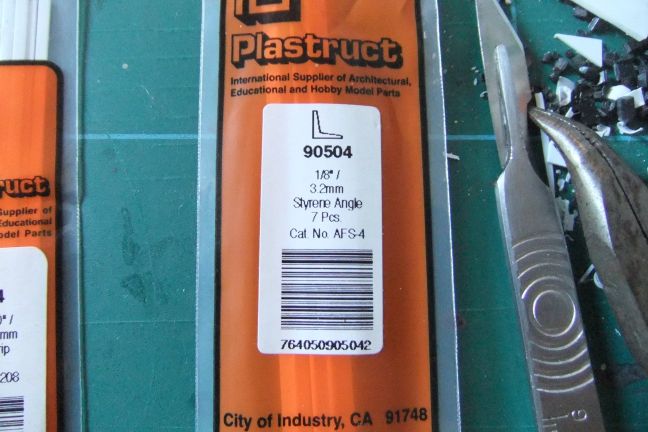
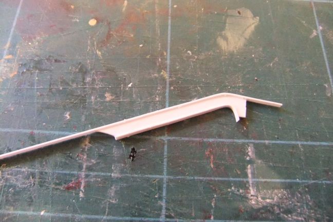
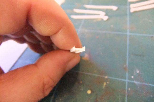
For the main side rails of the bridge arch, I used "L" shaped styrene rod... |
 |
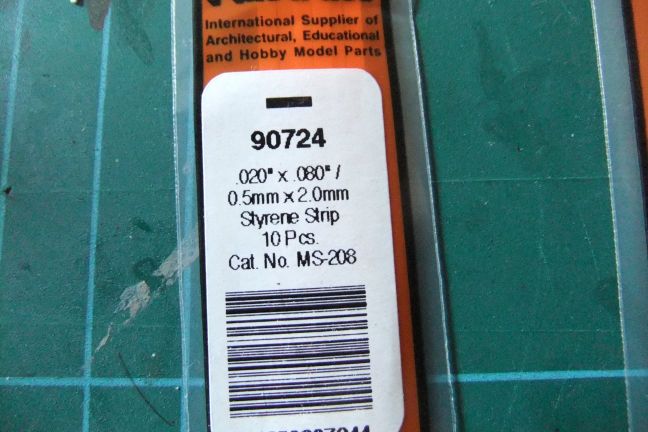
and I glued to the bottom of it, some 20thou x 80thou styrene strip |
 |
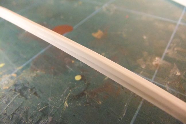
so that the two together formed an inverted "T" shape, with on long and one short arm. |
 |
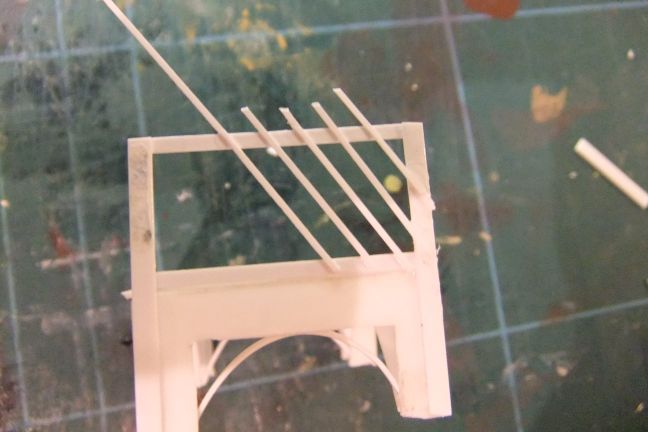
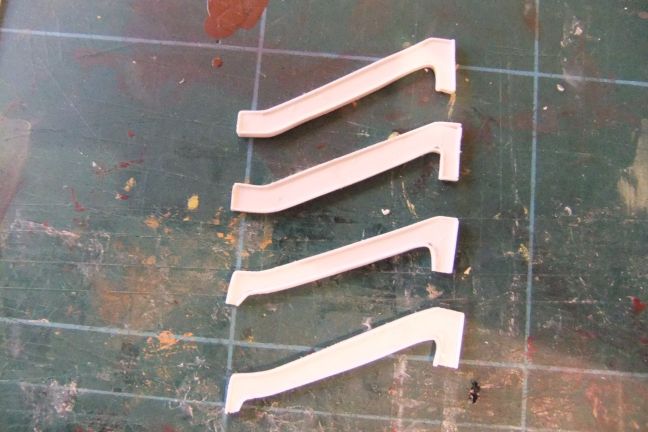
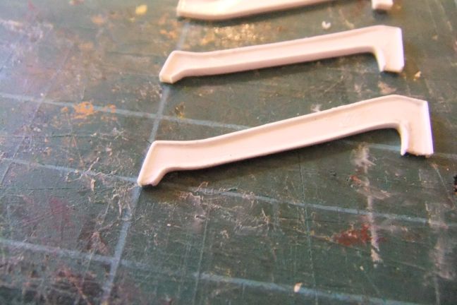
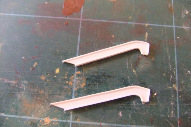
I then bent the rails to form the curvature of the bridge arch, by putting them in a jig made from a piece of wood and some nails, and then placing it in a domestic oven on a low light for 10 minutes. |
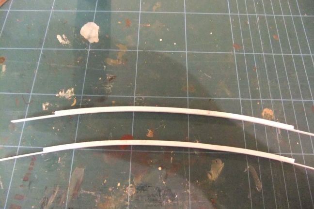 |
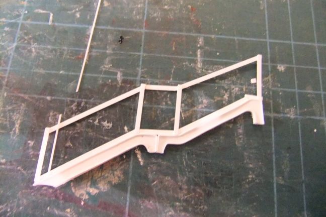
I did the same for both sides, and then added uprights made of 20thou x 40thou styrene strip, and then a top rail of 20thou x 60thou strip. |
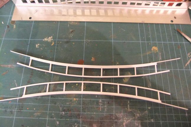 |
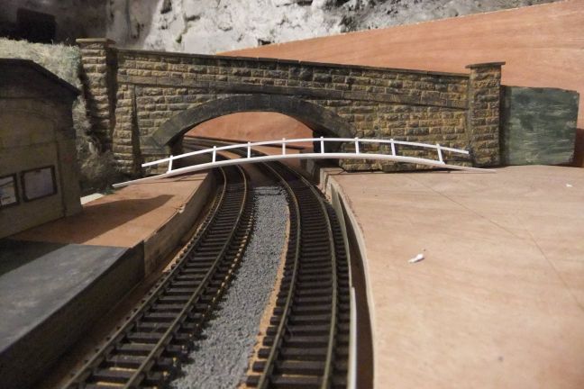
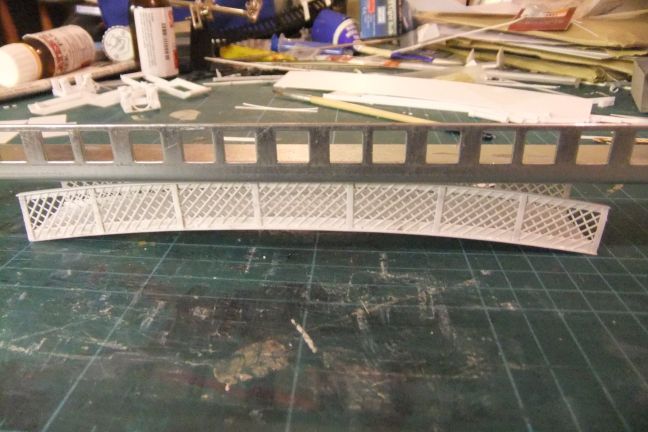
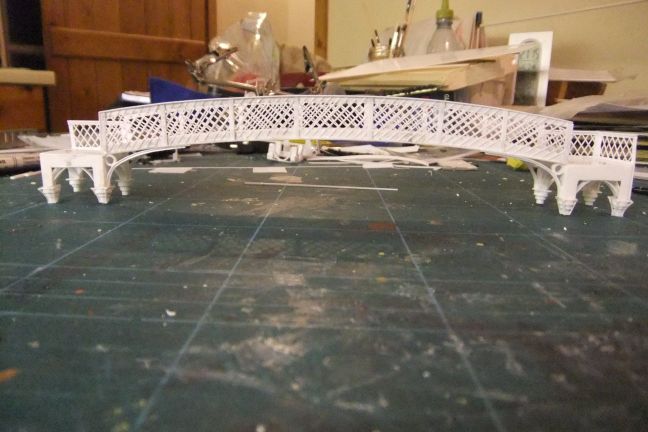
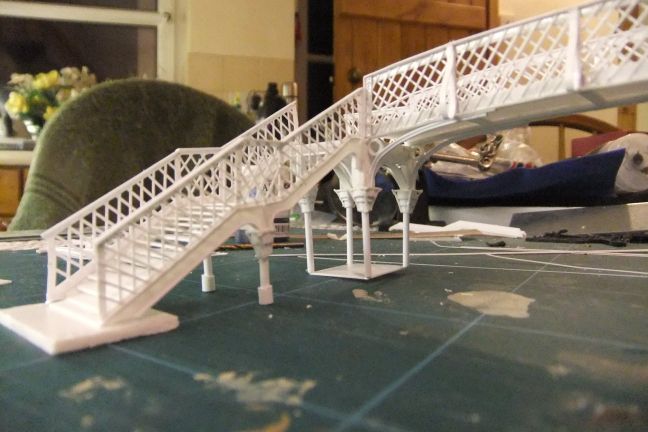
At this point, I took a side to the layout, to check the length of the arch was correct to fit across the platforms. |
 |
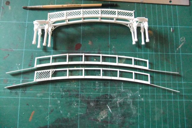
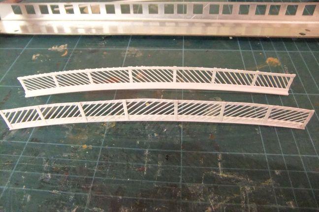
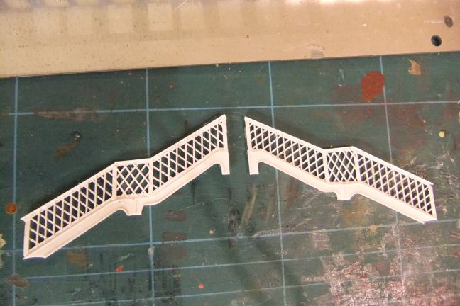
on the basis of that trial, I reduced the length of the two end bays, to match the centre ones. Here's a comparison with the mark 1 version... |
 |
You can see in the above photo, I had made a start on the lattice work. Here's a closer view. |
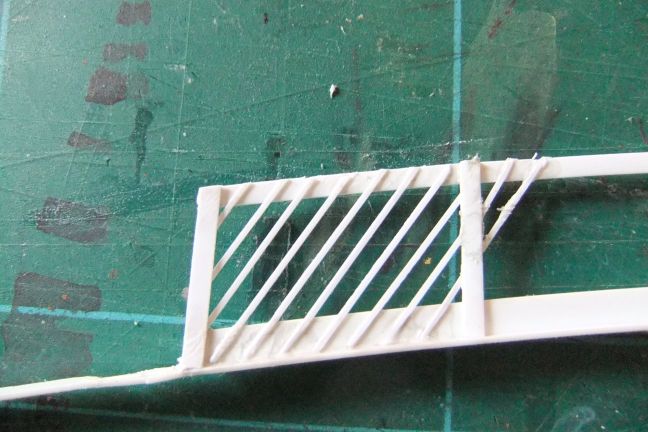 |
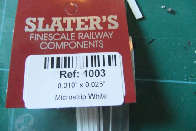
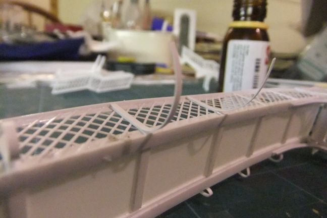
For the lattice, I used 10thou x 25thou styrene microstrip |
 |
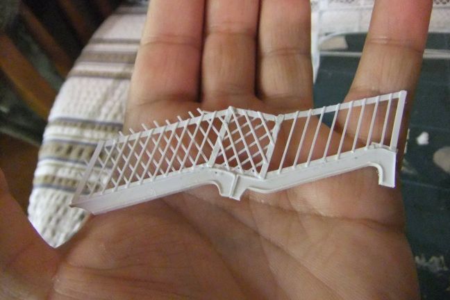
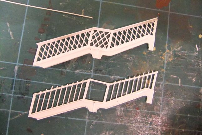
Here's the two sides, with the first run of lattice complete. |
 |
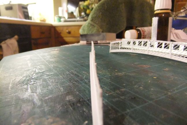
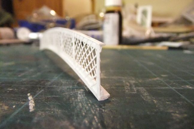
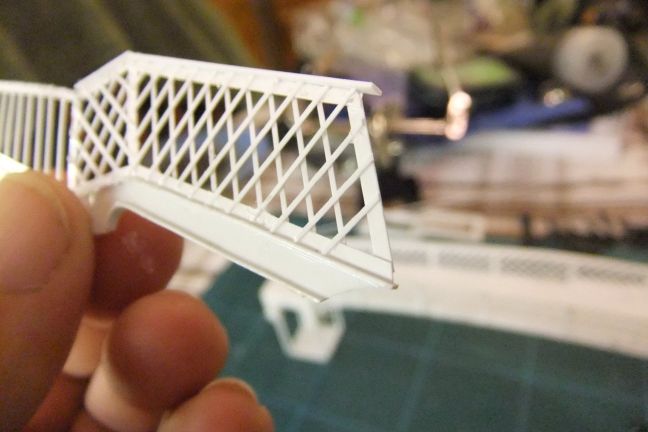
You can see the the side profile is really thin and to scale, and yet the arches are quite strong. |
 |
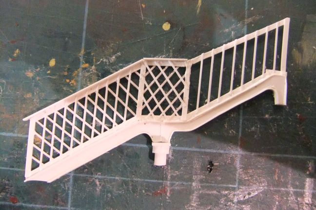
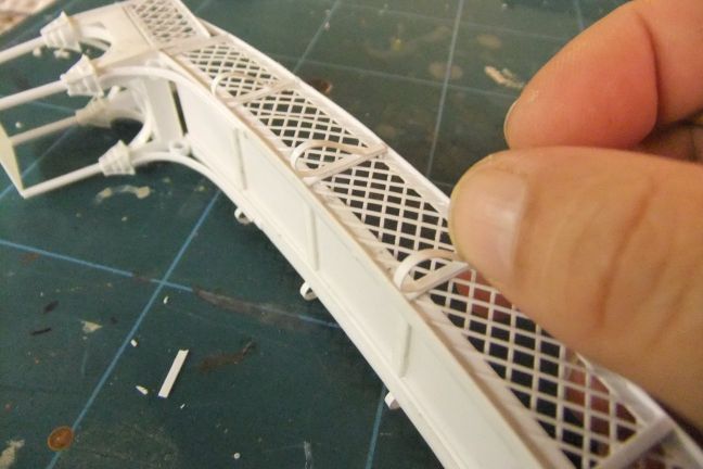
Here, I've now completed the second layer of lattice work on both sides. |
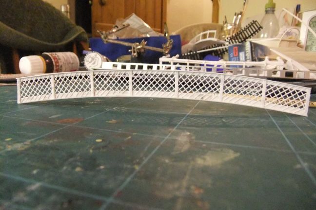 |
You can see in this picture how the lattice work is attached to each side of the top and bottom rails, as is the case with the prototype. |
 |
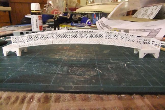
I attached the two sides together using 20thou styrene sheet. |
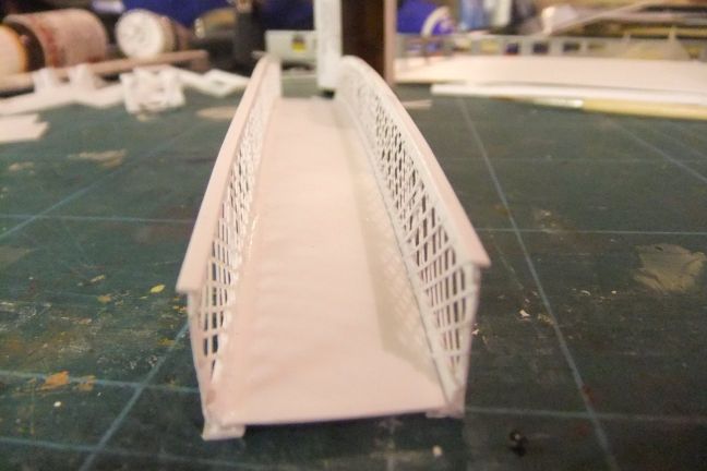 |
Once dried, the arch structure was quite robust. Here a length of steel is used to test the structure. |
 |
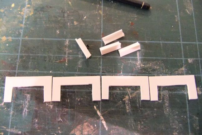
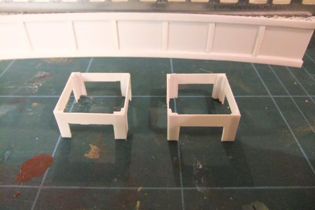
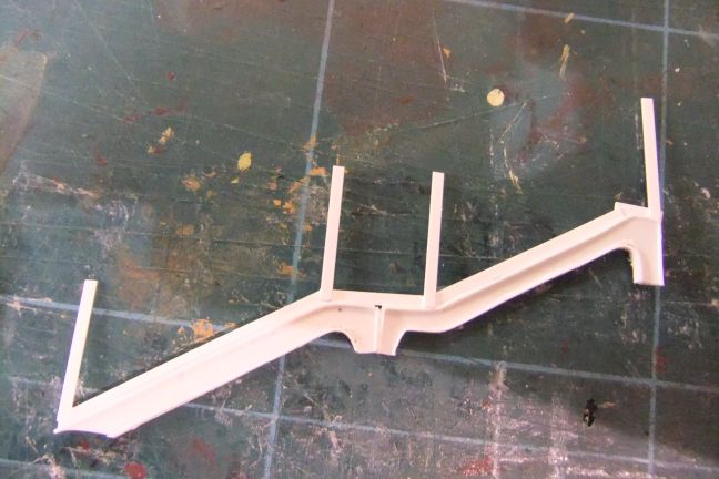
We now move on the the side columns which support the bridge. I started by cutting out these shapes from 20thou styrene sheet. |
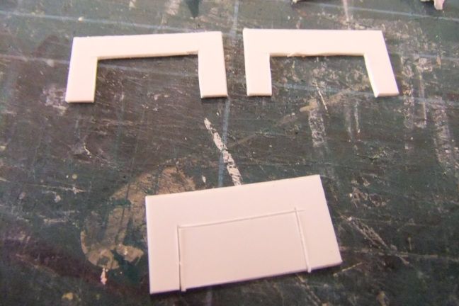 |
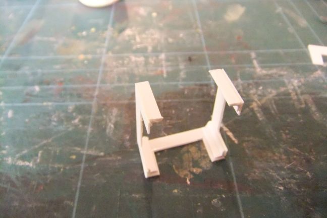
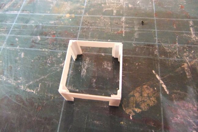
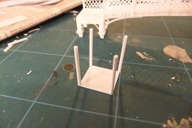
I then used some more of the "L" shaped styrene to join the cut out sections together to form two rostrum-like structures. |
 |
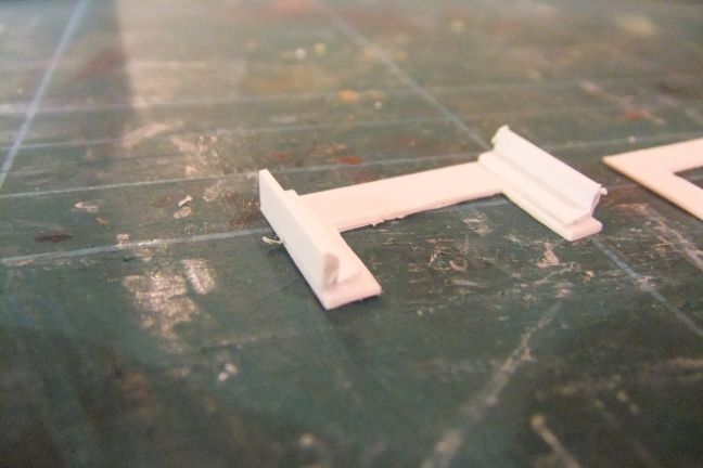 |
 |
 |
 |
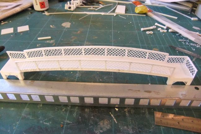
Although the sides were fairly robust, they did show some signs of warping, so I used the steel bar to keep it weighted down and straight. |
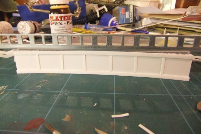 |
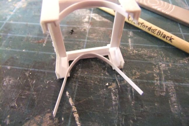
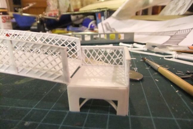
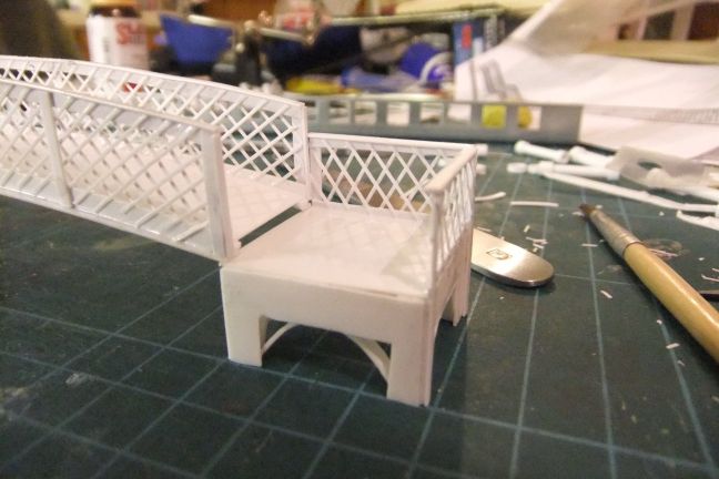
I added curved strips of 20thou to the underside of the platforms, to simulate the original ironwork |
 |
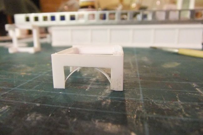 |
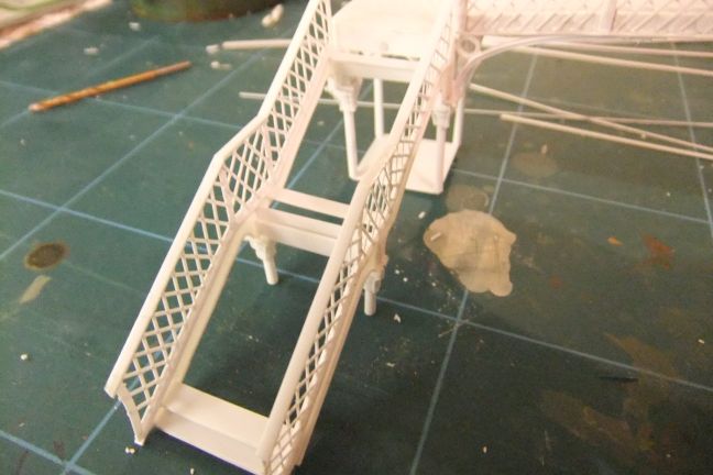
Then I began to add the sides and lattice to the two platforms |
 |
 |
 |
 |
 |
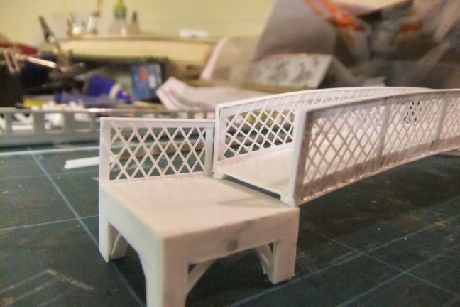
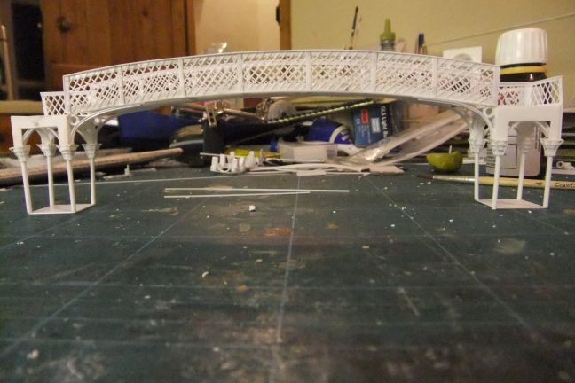
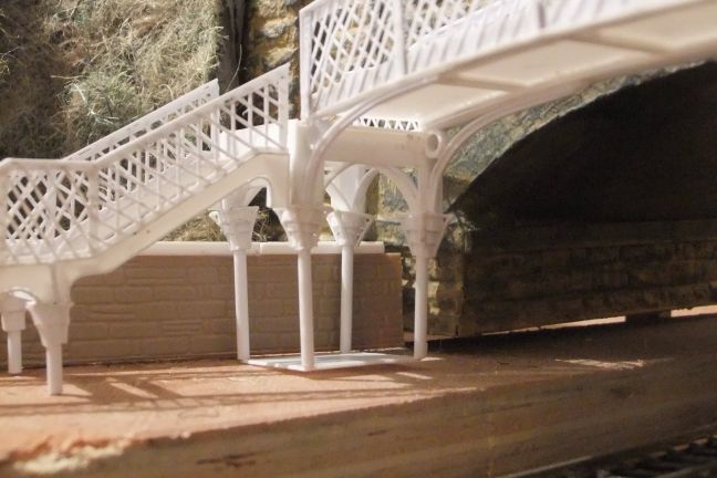
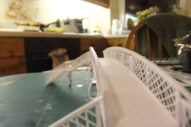
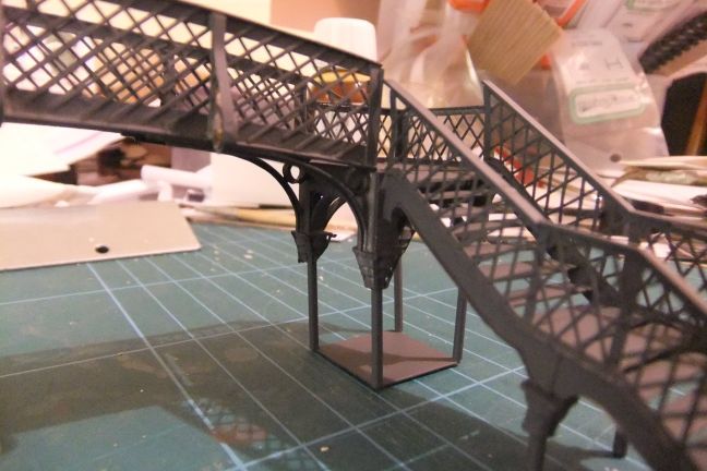
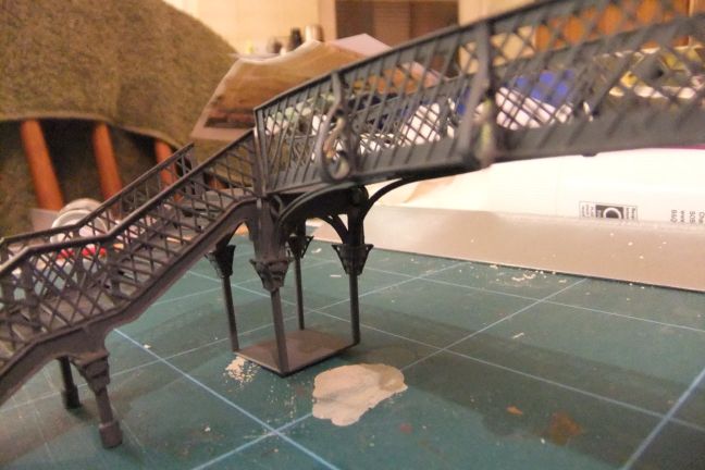
Once everything was completely set and stable, and using the steel bar as a straight edge, I joined the arch to the two platforms. |
 |
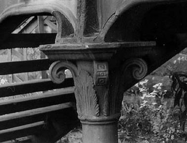
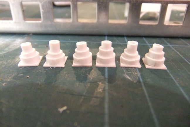
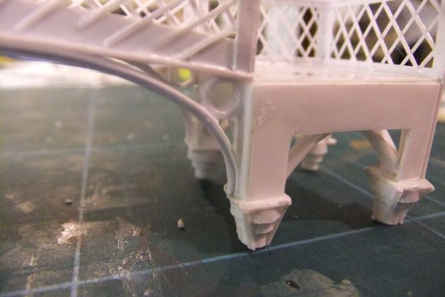
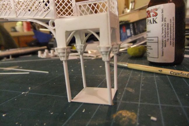
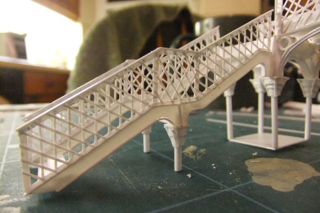
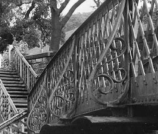
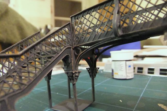
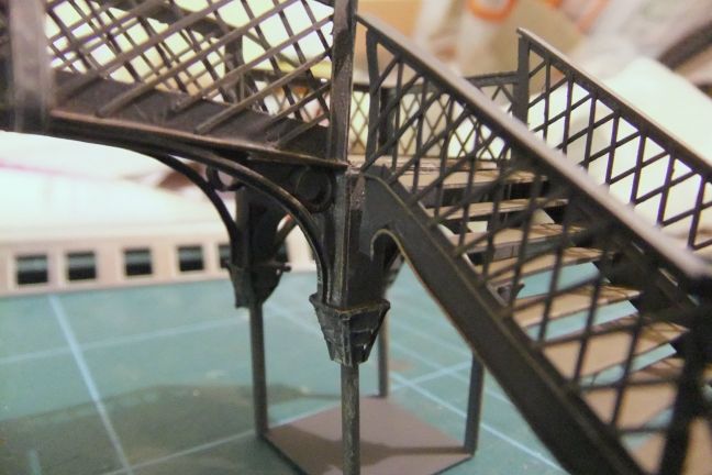
I wanted to try, as much as possible to capture the look of the wrought iron construction, and to that end, the footbridge has quite ornate capitals at the top of the supporting columns, as you see here: |
 |
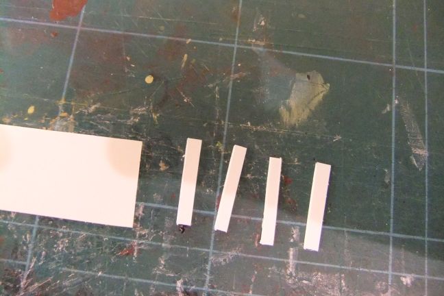
I wouldn't be able to model them exactly, but I thought I could give a suitable representation in the following manner: I took three sizes of styrene tube each fitting into the next, and cut them to length: |
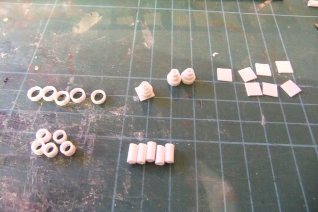 |
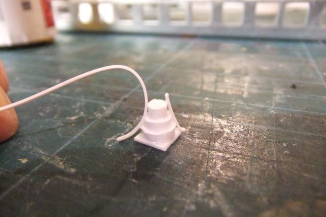
I then stuck them inside each other, and added a square base of 10thou styrene sheet. |
 |
Then I added lengths of 5thou microstrip on the corners |
 |
 |
In the same way, I wanted to capture the ironwork between the span of the arch and the platforms at each end. I used different sizes of microstrip, and thin slices of tube to mimic the look of the ironwork. |
 |
 |
 |
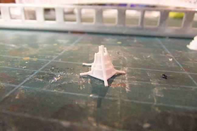
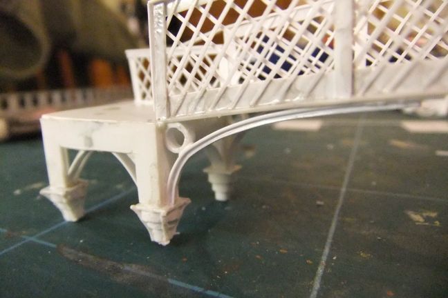
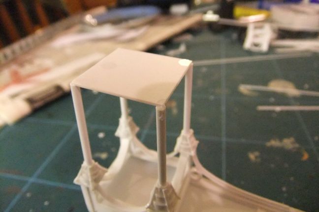
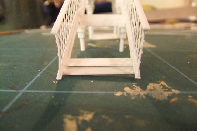
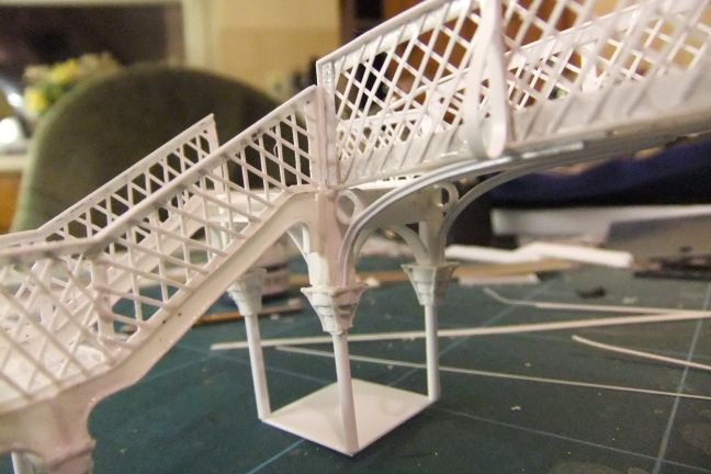
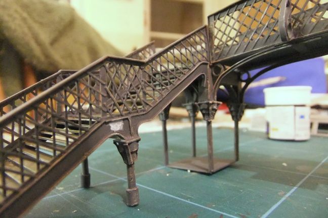
For the supporting columns, I used lengths of 2mm styrene round rod. I drilled out the capitals to accept the rod. |
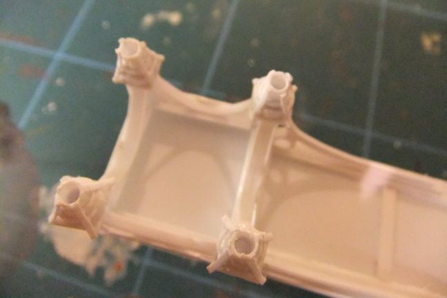 |
I used a square of 20thou styrene to join the corners of the columns to keep them square. |
 |
 |
 |
 |
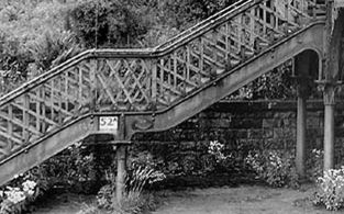
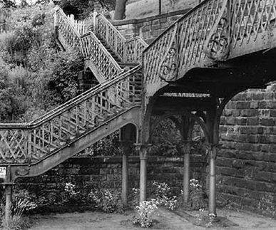
I now moved on to the side steps. You can see in the following picture how these are constructed from shaped pieces of cast iron, bolted together. Although probably taking things to extremes, I decided to create the model in the same way. |
 |
To begin with I cut out the basic shapes I wanted from 30thou styrene sheet. |
 |
Then I added 20thou x 80thou strip along the edges, to make an "I" shaped beam. First the top sections... |
 |
... and then the bottom. |
 |
 |
 |
Then I joined the top and bottom sections together. and added 10thou x 60thou strip as the bottom rail for the lattice, and uprights of 20thou x 40thou. |
 |
 |
And then it was back to latticing. |
 |
 |
 |
 |
 |
I started to cut the steps from a sheet of 20thou styrene |
 |
 |
 |
It was time to join the steps to the bridge structure. Here's what the real one looks like. |
 |
and here's a first attempt with the model. |
 |
As you can see, the steps sit too low on the structure. |
 |
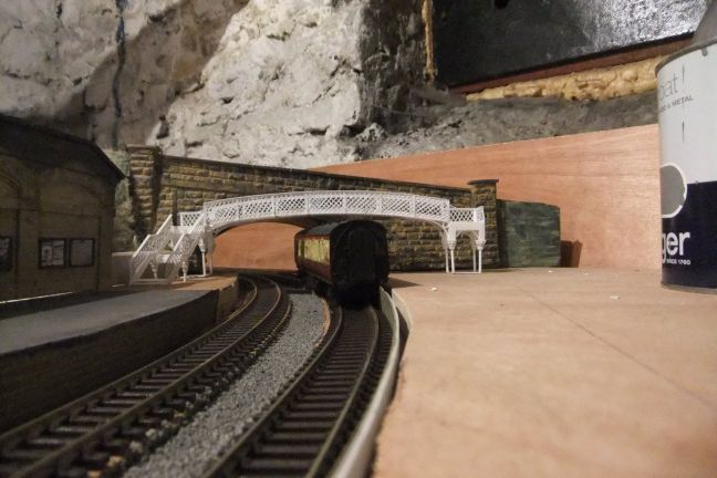
I placed the footbridge on the layout, to see if I could reduce the length of the columns, but on trying a coach under the bridge, it was obvious I needed all the length on the columns. |
 |
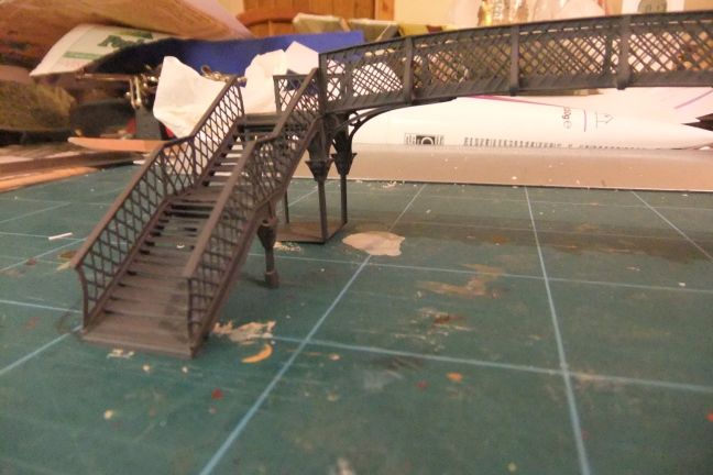
Instead, I added some 80thou styrene sheet under the steps, and extended the columns under the steps. |
 |
 |
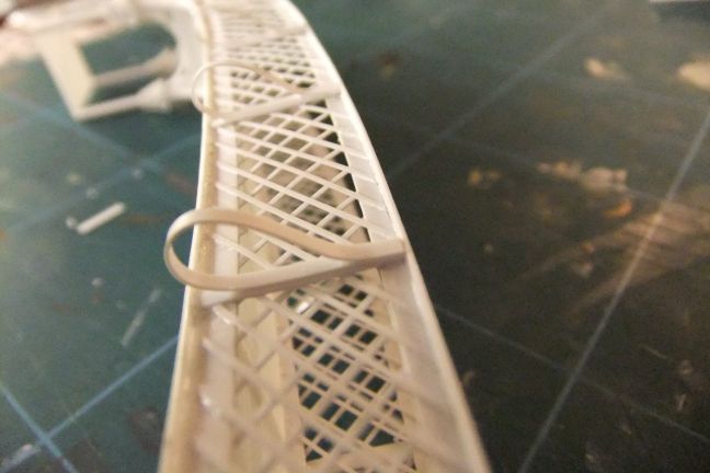
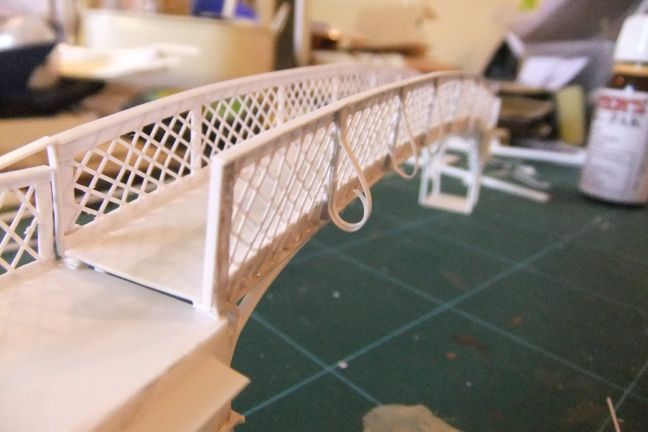
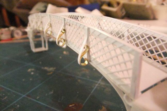
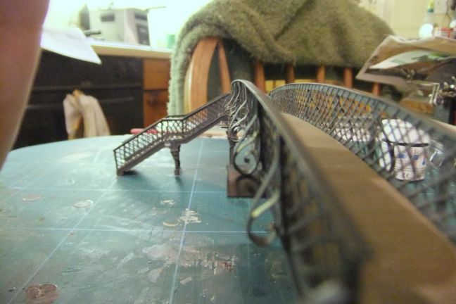
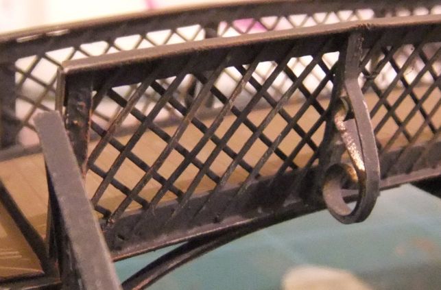
The side of the bridge span has these ornamental scrolls - there practical use is to add strength to the sides of the bridge. To model them, I used thin strips of styrene, for the outer loop. |
 |
 |
 |
 |
 |
For the internal scrolls, I tried to use the same styrene strip, but it wasn't a success. |
 |
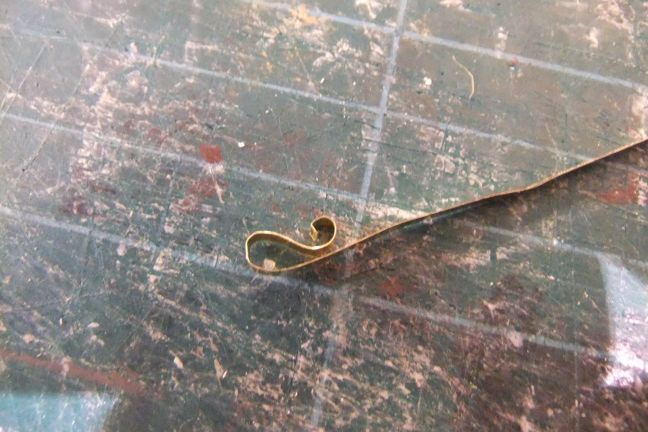
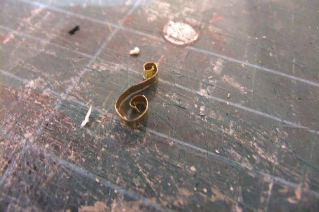
Instead, I used thin brass strip, which I formed into the shape of a musical treble cleff. |
 |
 |
 |
 |
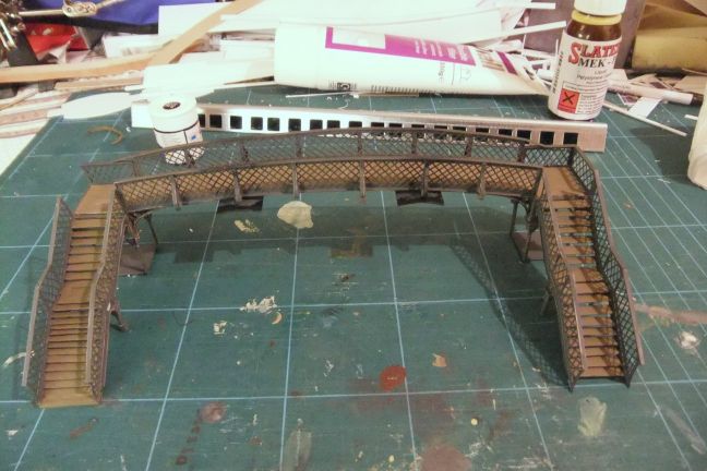
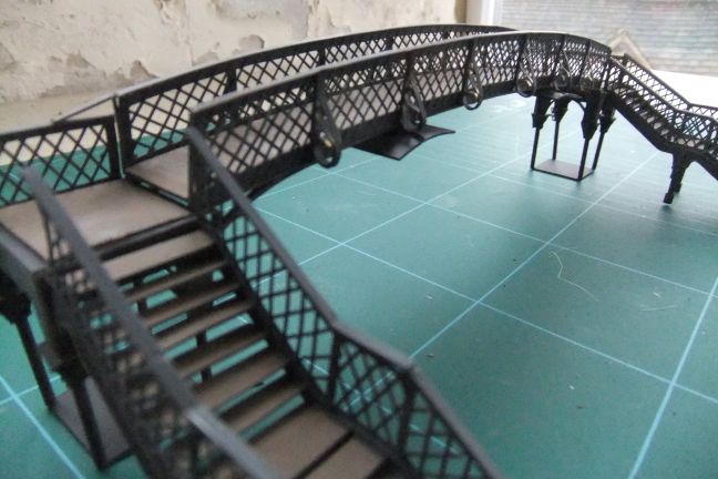
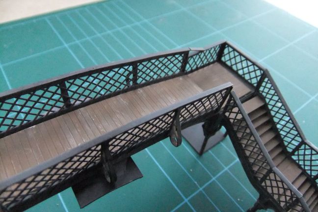
Construction of the bridge was now complete. |
 |
 |
Painting |
I sprayed the model all over with a dark grey acrylic, and then weathered it with dry brushes of Humbrol Matt Acrylic No.62 Leather (to represent rust), and Humbrol Metallic Silver No.11 |
 |
 |
 |
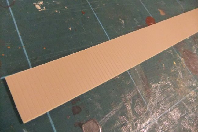
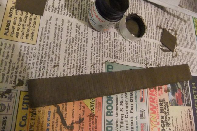
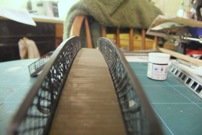
I added a strip of Slater's embossed styrene planking, to the bridge surface. |
 |
This was painted in Humbrol Matt Acrylic No.29 Dark Earth to represent old wood, and then weathered with Humbrol Matt Acrylic No.RC413 Engineer's Grey. The treads of the steps were similarly treated. |
 |
 |
 |
 |
 |
 |
 |
 |
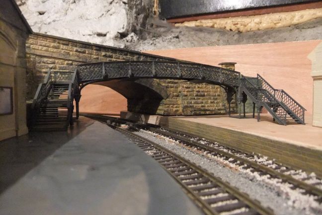
These were taken in natural daylight. |
 |
 |
 |